Difference between revisions of "Robotino3 PI controller"
From RobotinoWiki
(→Parameterisation) |
(→Parameterisation) |
||
| Line 70: | Line 70: | ||
|} | |} | ||
| − | With these parameters we get a response like shown in the | + | With these parameters we get a response like shown in the figure. Speed set-point is 1000 encoder ticks per motor revolution per smapling period of 1kHz. |
| − | [[Image:pid_controller_discrete_rect.jpg|thumb| | + | [[Image:pid_controller_discrete_rect.jpg|thumb|600px|center|PI controller response]] |
Revision as of 14:39, 1 October 2012
Discrete PI controller
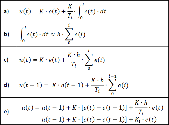
a) is the PI controller in continuous time domain form.
b) is the approximation of the integral by a discrete sum.
c) is the resulting discretised PI controller.
d) is the discretised PI control law time shift back one interval.
e) is derived by subtracting d) from c). e) is the so called velocity form of the discretised PI controller.
Implementation in Robotino's microcontroller
//K  - proportional gain
//Ki - gain
//ss - speed set-point
//y  - actual speed
//u  - control signal
//ud - decay factor to bring u down to zero in the case that err and ss are both 0 already
//up - u(t-1)
//ep - err(t-1)

float err = ss - y;

float u;

if( 0 == Ki )
{
	u = K * err; // There is no integral term
}
else
{
	u = motor_uant[motor] + K * (err - motor_errant[motor]) + Ki * err;
}

if( 0 == ss && 0 == err )
{
	u *= ud;
}

if( u < 1.0f && u > -1.0f )
{
	u = 0;
}

up = u;
ep = err;

if( u > 255.0f ) u = 255.0f;
else if( u < -255.0f ) u = -255.0f;
Parameterisation
The default parameters are:
| Name | Value |
|---|---|
| K | 8 |
| Ki | 0.25 |
| ud | 0.01 |
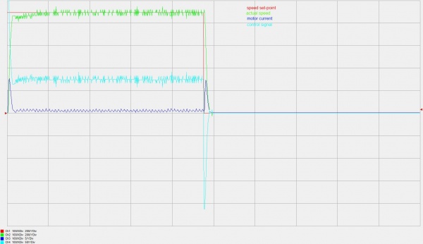
With these parameters we get a response like shown in the figure. Speed set-point is 1000 encoder ticks per motor revolution per smapling period of 1kHz.

